Drawing an electronic schematic in KiCad is an odd mix of two things: a small amount of thinking about the circuit, and a huge amount of mechanical work — placing every part, running wires so they don't cross, adding ground symbols, nudging labels until they're readable, and doing it all again every time you change your mind. MCP-KiCad is an MCP server that gives Claude the ability to do that second part for you: you describe the circuit in plain language and get back a real .kicad_sch file that you open in KiCad and edit like any other. The project lives at github.com/unmateria/MCP-Kicad.
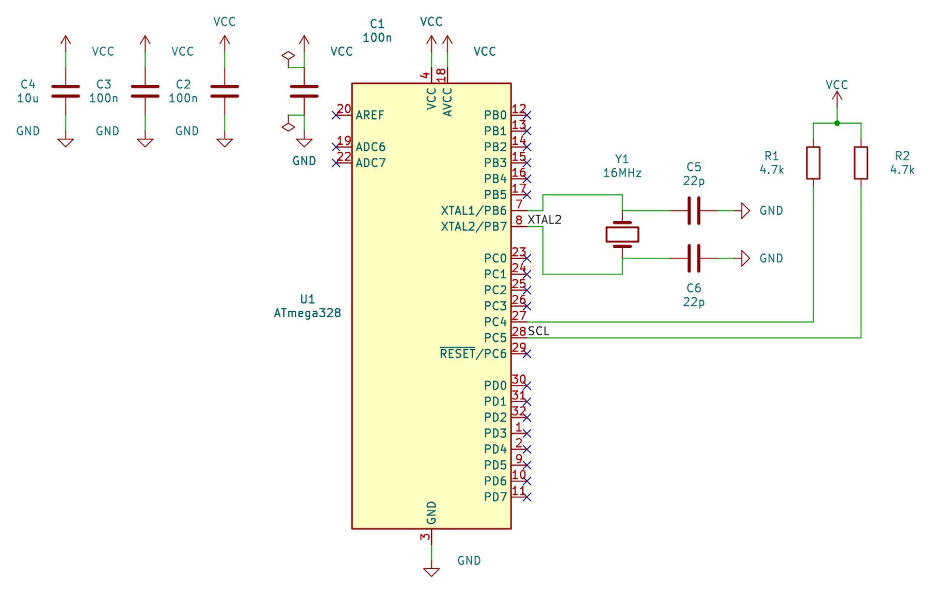
01 — The problem: the boring part of a schematic is most of the work
When you build a simple circuit — a 555 timer, a regulated supply with a 7805, a minimal microcontroller board — the interesting part takes five minutes. You know a 555 in astable configuration needs two resistors and a capacitor, you know the frequency comes from a formula, and you know there should be a 10 nF cap on the control pin. That's the circuit, and that's what's in your head.
What comes after is where the time goes. You open KiCad, hunt for each symbol in the library, place it, rotate it, nudge it because it doesn't line up with the next one, run a wire, notice it crosses another one, redo it, add a ground symbol for every pin that goes to ground, position the reference labels that landed on top of the parts, move them one by one… and when you're done you realise you wanted that resistor somewhere else, and half the sheet falls apart.
None of that work is hard. It's tedious, repetitive and perfectly mechanical, which is the exact definition of something a machine should be doing. And that's where it gets interesting: today's language models understand perfectly well which circuit you want. What they cannot do on their own is draw it properly.
02 — What an MCP is, and why it changes the rules
MCP stands for Model Context Protocol, a standard published by Anthropic so AI assistants can talk to programs running on your machine. The underlying idea is simple but it changes a lot.
Without MCP, working with an AI is a manual round trip: you ask for something, it replies with text, and you copy that text wherever it needs to go. Ask it for a KiCad file and you get a pile of parentheses that you have to paste into a file, save, open in KiCad and hope it doesn't error out. When it fails — and it does — you start over.
With MCP, the assistant gets a direct channel to a program that knows how to do specific things. That program (the MCP server) runs on your machine and exposes a list of tools: well-defined functions the AI can call whenever it sees fit. The AI doesn't write the file: it requests operations and the server carries them out for real, in ordinary code, checking what it does.
That distinction is the key to everything that follows. A language model is excellent at deciding which parts are needed and how they connect. It is terrible at computing millimetre coordinates and predicting whether the wire from pin 3 to pin 7 will crash into the body of an IC. So the division of labour writes itself: the model decides the circuit, the server computes the geometry. And the server, being ordinary code, can check its own work before handing it over.
03 — What MCP-KiCad actually does
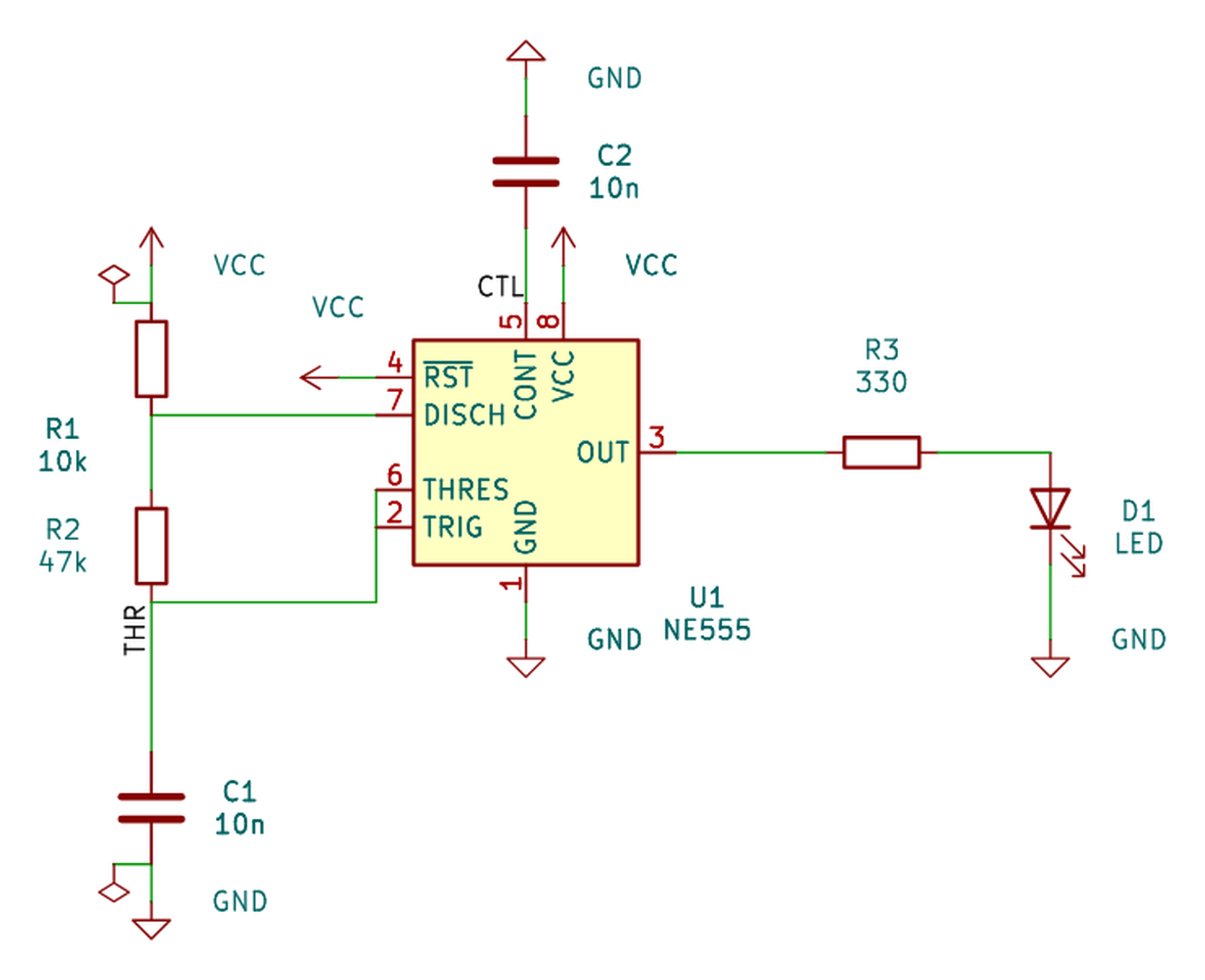
You ask for a circuit in plain language. Claude writes a structured description of it and calls one tool, compile_schematic, which turns that description into a finished schematic. The conversation looks like this:
You:    Build me a 555 astable blinking at 1 Hz, 5 V supply.

Claude: [looks up the real pin names of the NE555 in your library,
         writes the design and compiles it]

        Done — 7 components, ERC clean, netlist verified.
        Here's the preview.
The result isn't a picture or a drawing: it's a real .kicad_sch file you open in KiCad like any other, with a correct netlist, ready to take to a board. You can keep editing it by hand, add things to it, or ask Claude to change it and recompile.
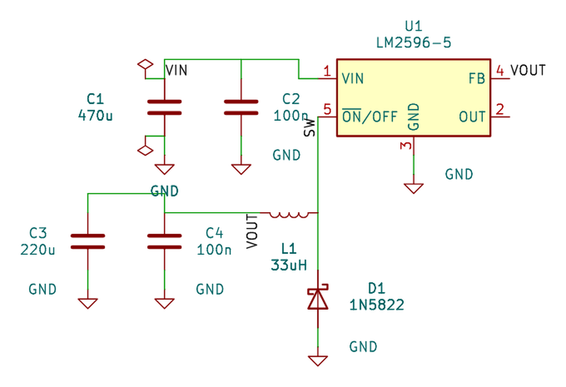
Besides compiling whole circuits, the server exposes another thirty-two tools for working on existing schematics: searching your KiCad libraries for parts, listing the real pins of a symbol, reading a schematic and reporting how it's connected, moving things around, running ERC, exporting to PDF or an image. In practice almost everything happens through compile_schematic; the rest are there for inspection and repair.
04 — Why most AI attempts go wrong
Getting a language model to emit a .kicad_sch file is easy. The problem is the result is almost always garbage, and it's worth understanding why, because it explains every design decision in this project.
The visible failures are the ones you'd expect: wires crossing over unrelated wires, wires running clean through the body of an IC, reference text piled on top of components, overlapping symbols. All of that is ugly, obvious at a glance, and fixable by looking at the drawing.
But there is a far worse failure, and it's the one that should scare you: the silent short. In KiCad, a wire that ends exactly on a component's pin is connected to it. If the model miscalculates a coordinate and a wire endpoint lands right on a pin belonging to a different signal, KiCad merges the two signals into one. And here's the nasty part: the result is perfectly consistent. There's no odd crossing, nothing looks bent, the file is valid, ERC won't necessarily complain. The schematic has simply stopped being the circuit you asked for, and nothing in the drawing gives it away.
That's why "just check it looks right" isn't enough. A schematic can look immaculate and be wrong. Something else has to be checked.
05 — The guarantees: why you can believe this schematic
The founding decision of the project is that the model is never asked to draw. It's asked to describe: which parts there are and which pins connect to which. That description contains not a single coordinate. Positions are expressed by anchoring one part to another part's pin, a whole number of 2.54 mm grid cells away — which is, incidentally, how a human thinks when placing parts on a grid.
From there the compiler takes over: ordinary code, deterministic and checkable. And before the file reaches you it goes through several filters:
- A geometric gate re-examines every wire segment drawn. If a wire crosses another signal, cuts through a symbol body, overlaps another one collinearly, or runs over a pin it doesn't belong to, that wire is deleted and the connection is remade with net labels. Electrically identical; aesthetically worse. But never a lie.
- The netlist is verified by rebuilding it. Once the file is finished, it's read back from scratch, traced to see what connects to what, and compared against what you asked for — in both directions. Every connection you declared must exist, and no connection you didn't declare may. If anything differs, the build fails and says so, instead of handing you a good-looking schematic.
- Power symbols are checked by physical contact, not by name. KiCad joins every ground by the name
GND, so a ground symbol stranded in the middle of the sheet looks connected if you only inspect names. It's verified that it really touches the pin it claims to touch. - And KiCad has the last word.
kicad-cli— the official command-line tool — runs ERC, and the report comes back with the result.
One implementation detail is worth mentioning because it's common sense and almost nobody respects it: KiCad files are read and written with a real parser, never by searching and replacing text. A .kicad_sch is a tree of parentheses (an S-expression, like Lisp). Manipulating it with regular expressions works right up until the day it doesn't and wrecks your file. Here it's parsed whole, the tree is modified in memory, and it's written back out.
The practical consequence is that the .kicad_sch is treated as a build artifact, like a compiled executable: you don't edit it by hand, you edit the description and recompile. Want to change the circuit? Change two lines of text and rebuild the whole thing in a second, instead of dragging parts around with the mouse and wrecking half the sheet.
06 — Step-by-step installation
You need KiCad 10 installed, because the server relies on kicad-cli — the command-line tool that ships with it — to run ERC and generate previews. And you need Claude Desktop or Claude Code. Nothing else: the server is a single executable with no external dependencies.
There are two ways to install it.
The easy one, a single click. Download mcp-kicad.mcpb from the downloads page and double-click it. Claude Desktop installs it as an extension: no configuration file to edit, no paths to type. That one file carries the Windows, macOS and Linux builds inside, so it works on any system.
The manual one, with the plain executable. If you'd rather control where the program lives, the releases page has the loose binaries:
mcp-kicad-windows-amd64.exe— Windowsmcp-kicad-linux-amd64— Linux on PCmcp-kicad-linux-arm64— Linux on ARM (Raspberry Pi and friends)mcp-kicad-darwin-arm64— macOS on Apple Siliconmcp-kicad-darwin-amd64— macOS on Intel
Put it wherever you like, say C:\Tools\. On Linux and macOS you'll need to make it executable with chmod +x, and on macOS also unblock it the first time with xattr -d com.apple.quarantine, since the binary isn't signed.
There's nothing to configure. The server finds KiCad on its own: on Windows it looks in C:\Program Files\KiCad\, on Linux in /usr/bin and /usr/local/bin, on macOS inside /Applications, and failing that it tries the PATH. Only if your install is somewhere unusual will you need a config.ini next to the executable, and the repository ships a commented example.
07 — Connecting it to Claude Desktop
If you used the one-click installer this is already done and you can skip ahead. If you took the plain executable, you need to tell Claude Desktop where it is. Edit its configuration file, which on Windows lives at %APPDATA%\Claude\claude_desktop_config.json, on macOS at ~/Library/Application Support/Claude/ and on Linux at ~/.config/Claude/. Create it if it isn't there:
{
  "mcpServers": {
    "kicad": {
      "command": "C:\\Tools\\mcp-kicad.exe",
      "args": []
    }
  }
}
Two warnings that save grief. First: in JSON, Windows backslashes must be doubled — C:\\Tools\\, not C:\Tools\. A single one is by far the most common reason the server won't start and you can't tell why. Second: after saving you must quit Claude Desktop completely and reopen it. Reloading the window won't do, because the server is launched as a child process and only starts on a full restart.
On Claude Code it's a single command:
claude mcp add kicad -- /path/to/mcp-kicad
To check it works, ask Claude: "use get_project_info to check the KiCad setup". It should report the kicad-cli path it detected, the library directories, and the folder where generated files will land.
08 — How you actually use it
You describe the circuit, and that's it. The more specific you are about what matters to you — supply voltage, particular part numbers you want, values you've already settled on — the less it has to assume. Things that work well:
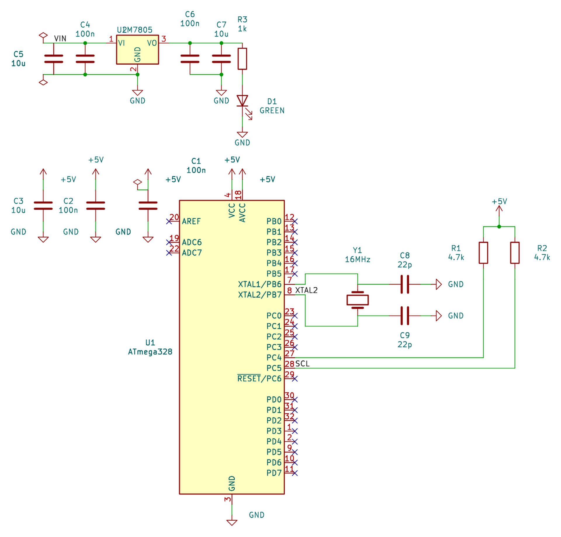
Design a 5 V regulated supply from a 12 V input using an LM7805, with
input and output decoupling and a power LED.

Make me a minimal ATmega328P board: 16 MHz crystal with load caps,
reset pull-up, ICSP header, and decoupling on both supply pins.

Build a two-transistor astable multivibrator that blinks two LEDs at
roughly 2 Hz.
And once you have the schematic the conversation continues: "show it to me" renders a preview, "export it as PDF" gives you a vector PDF, "run ERC" runs KiCad's electrical rules check and explains the violations if there are any, and "move the decoupling caps closer to U1 and recompile" does exactly that. Because the design source is text, revising is dirt cheap: changing your mind costs a sentence, not half an hour of dragging things around.
09 — Under the hood: the design source
You never need to touch this, but it's worth seeing because it explains where the stability of the result comes from. What Claude actually writes is a document like this:
{
  "version": 1,
  "project": "led_18650",

  "blocks": [
    {
      "name": "led",
      "symbols": [
        { "ref": "BT1", "lib": "Device:Battery_Cell", "value": "18650" },
        { "ref": "R1", "lib": "Device:R", "value": "100", "rot": 90,
          "place": { "pin": "1", "at": "BT1.+", "dir": "up", "cells": 1 } },
        { "ref": "D1", "lib": "Device:LED", "value": "LED_RED", "rot": 90,
          "place": { "pin": "A", "at": "R1.2", "dir": "right", "cells": 3 } }
      ]
    }
  ],

  "nets": {
    "VBAT":   ["BT1.+", "R1.1"],
    "_ANODE": ["R1.2", "D1.A"],
    "GND":    ["D1.K", "BT1.-"]
  },

  "power_nets": { "GND": "power:GND" }
}
Notice what isn't there: millimetres. The first part in each block is the anchor, and every other one hangs off a pin of one already placed, so many grid cells in a given direction. "R1's pin 1 sits one step above the battery's positive terminal." That's the whole language.
Expressing positions that way is what makes the result stable. If you asked a language model for coordinates, every rebuild would give you a slightly different drawing with different mistakes. Anchored pin to pin, the schematic stays on the 2.54 mm grid and the spatial relationships survive no matter how things get reordered. And since it's plain text, you can version it in Git, diff two revisions, or spin off board variants by changing four values.
10 — Four things KiCad doesn't do the way I thought
This section is for anyone wrestling with something similar, because each of these four cost me time. All four were written into the code as certainties, and all four turned out to be false when measured. None was discovered by reasoning: they all came from exporting the netlist and the graphics with kicad-cli and looking at what KiCad had actually done.
- A wire crossing a pin tip mid-segment does not connect to it. One that ends there does. That asymmetry is exactly the silent short described earlier, and it's what forces you to check the endpoints of every segment.
- Mirroring is applied after rotation, reflecting the finished placement, not before. It makes no difference at 0° and 180°, and gives different results at 90° and 270°. I had it backwards, and the test that checked it was written using my own wrong convention, so it happily confirmed the error.
- What aims a label's text is the justification, not the angle. The angle only picks the axis. Rotating a label without touching the justification moves absolutely nothing — and I had a whole function dedicated to rotating labels that had been doing nothing at all for a long time.
- In a KiCad-exported SVG, the text elements are invisible. They're there at full transparency, as selection helpers. What's actually drawn are the vector strokes in a different group. If you measure text boxes to find out whether two labels overlap, you're measuring something nobody can see.
The moral, which applies to any project like this: when you're unsure what a tool does, measure it. Don't reason it out, don't remember it, don't infer it from the documentation. Run it and look at the result.
11 — What it does not do
Worth being clear about this, because the name can mislead.
It does no PCB work at all. No footprint placement, no track routing, no Gerbers for manufacturing. That isn't an oversight, it's deliberate. A board built from a schematic you can't trust is worth nothing, so I'd rather not touch copper until the schematic side is genuinely solid. It's the natural next step for the project, and the recipe that worked for schematics — declarative description, deterministic compilation, geometric gate and verification against the official tool — should apply just as well to the board.
It doesn't invent parts. It uses the symbol libraries you already have installed with KiCad, which run to thousands. If you need something that isn't there it can fetch it from SnapEDA given an API key, but it doesn't conjure symbols out of nothing.
It is not a simulator and it won't tell you whether your circuit is a good idea. It draws what you describe. Ask for a supply with no output capacitor and you'll get a supply with no output capacitor. The design judgement stays yours.
And there are known rough edges, which I'd rather tell you than have you discover. On very dense sheets text still overlaps sometimes: each label is moved to the lowest-overlap position available, but on a crowded schematic the best available spot still touches something. The compiler tells you exactly what's left overlapping and how much extra spacing would clear it. And some connections come out as labels rather than wires, which is the geometric gate doing its job: it prefers a correct label to a pretty wire that lies.
Finally, the platform it's genuinely tested on is Windows. The Linux and macOS builds compile and detect KiCad correctly on each system, but I haven't run them on real hardware, so if you use them and something breaks, tell me.
12 — Who this is for
Thinking about who gets real value out of it:
- The hobbyist who knows electronics but fights with KiCad. You know exactly what circuit you want, but the program feels hostile and every schematic eats an afternoon. Here you describe the circuit and it comes out drawn; and since the file is perfectly ordinary, you can keep editing it by hand wherever you don't like it.
- Anyone making many variants of the same design. If you build similar boards with four values changed, having the circuit in a text file that compiles is a huge difference from duplicating projects and hand-editing every copy.
- Anyone learning. Being able to ask for "a voltage divider with feedback" and see it drawn properly, with grounds and labels where they belong, is a fast way to pick up schematic conventions.
- And anyone curious about the problem itself. The underlying question — how to get a language model to produce something geometrically correct and verifiable, rather than something that merely looks correct — is interesting well beyond KiCad. The code is all on GitHub, commented, with the decisions explained.
What it is not: a substitute for knowing electronics. You still have to decide the circuit, pick the values and understand what you're building. What disappears is the friction between having the circuit in your head and having it drawn properly, which in my case was the part of any project I dreaded most.
The project is at github.com/unmateria/MCP-Kicad, with downloads for every system on its releases page. If you try it and something grates — a drawing convention I've got wrong, a circuit that comes out odd — tell me, because that's exactly what I can't check on my own.